Membrane bioreactor
Membrane bioreactor
MBR (Membrane Biological Reactor) FOR THE BIOLOGICAL PURIFICATION OF WASTEWATERS
In Italy, the enforcement of Legislative Decree 258/00, assimilating EU Directives 271/91 and 676/91 and the recent Decree issued by the Ministry of the Environment and the Protection of Land and Sea No 185 of 12 June 2003, establishing the technical standards for reuse of waste water, has led to the introduction of more stringent regulatory limits regarding the removal of nutrients from effluents. In particular, the concept of a 'sensitive area', conceived as a receiving body of water exposed to the risk of eutrophication, boosted the need for revamping existing water treatment plants, often characterized solely by compartments for the biological oxidation of organic compounds.
However, this need for enhancement tends to clash with lack of availability of surface areas for the execution of conventional activated sludge purification processes, encouraging a growing interest on the part of operators in treatments capable of rendering the volumetric characteristics of processes more compact and of optimizing the quality of purified water, at the same time simplifying plant management.
Membrane biological reactors (MBR) derive from the combination of traditional suspended biomass processes with filtration processes on microporous or ultraporous membranes, depending on the nominal size of the pores. The major advantages deriving from this technology are to be found in the possibility of eliminating the sedimentation unit downstream biological compartment and all management and operational constraints related to it.
The replacement of the sedimentation compartment with a membrane filtration compartment involves:
- a considerable reduction in the planimetric layout of the purification system due to both the disappearance of the clarifier and to the increase in the concentration of sludge in the biological reactor;
- the possibility of managing the biological process in a manner totally independent from fluctuations of the hydraulic load (the cell residence time and hydraulic retention time are entirely unrelated);
- the reduction of excess sludge associated with the highest values ?of sludge age;
- the elimination of problems relating to the sedimentation capacity of sludge common in traditional actiated sludge systems.
- the significant improvement of the qualitative characteristics of the effluent compatible with the potential re-use of purified water.
Membranes for submerged installation in oxidation tank
Hollow fiber polymeric membrane: porosity 0.1 micron and internal fiber diameter of 0.3 mm.
Membranes for installation outside the oxidation tank
Tubular polymeric membrane: porosity 0.03 micron, channel diameter 8 mm.
Ceramic membrane: porosity 0.05 micron, equivalent diameter for channels 3.5-6 mm.
Submerged hollow fiber polymeric membrane
The filtration modules are formed by hollow fibers supported on a robust frame in stainless steel and connected by means of PVC collectors.
The support structure of the modules serves to make the system rigid. The height of this structure is nevertheless sufficient to ensure that the fibers remain rather 'soft', that is, capable of moving under the action of the air blown from beneath the module; in fact, the modules incorporate a second collector for air distribution under the fibers by means of a blower.
Flowing in the form of bubbles along the fibres, air generates a turbulence around them which helps to keep the fibers clean.
The modules are fully immersed in oxidation tanks (or rather in specific dedicated compartments that are mantained in communicaton by means of valves, such as to enable their separation for membrane maintenance).
Typically, in addition to the membrane modules each system includes:
- An extraction pump for the permeate (and any air trapped inside the fibres), which is reversible and able to generate 0.4 - 0.5 bar during extraction. This pump will create a depression in the head connectors where the fibres are sealed with epoxy resin.
- An airing system to provide air to the membranes. Air is supplied in the form of large bubbles through specific diffusers located below the membrane modules.
- A 'clean-in-place' circuit, with a washing products tank and a dedicated pump when required.
- A backwash system where required.
In case of submerged membrane bioreactors, final sedimentation and sand filtration stages are replaced, solving all problems of poor sedimentation of activated sludge. This also makes it possible to work with sludge concentration in oxidation tanks much larger than that of traditional systems (up to 8-10 gMLSS/lt as opposed to the the traditional 4 gMLSS/lt), with all related advantages.
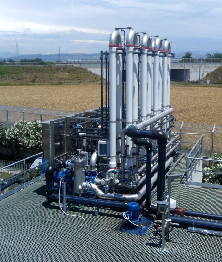
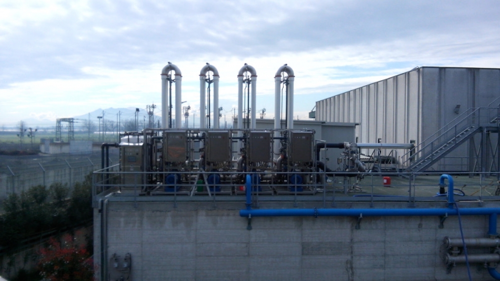
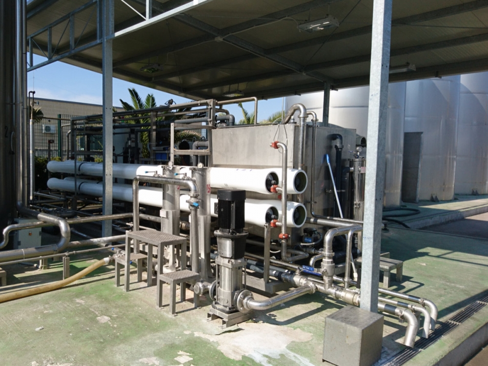
External tubular polymer membrane
Main characteristics of the tubular membranes:
| MEMBRANE MATERIAL | PVDF |
| POROSITY | 0.03 micron |
| TUBE DIAMETER | 5-8-10 mm |
| MAX PRESSURE: | 8 bar |
| WASHING CONDITIONS (pH) | 2 |
| WASHING CONDITIONS (TEMPERATURE) | T max = 60°C |
| BACKWASHING | YES |
Tubular membranes are characterized by low hydraulic resistance and consequently high permeability, even at low operating pressures. Filtration takes place from inside towards the outside of the fibres and, given the size of the channels, this process is sustainable even at high concentrations of suspended solids (20 g/l of biological sludge) without any risk of obstruction and blockage. Designs different from the standard versions are available. The internal diameters of available fibers range from 5 to 12 mm.
The tubular membranes are encapsulated in cylindrical fiberglass modules with an epoxy-resin seal.
The plant features a cross flow configuration, i.e. with fluids pumped into the module. The shear stress on the inner walls of the fibers due to the passage of fluids controls the formation of deposits that would limit permeability. It is also possible, using different techniques, to introduce air bubbles inside the fibers, further increasing the flows of permeate that can be obtained.
The specific flows of permeate obtainable range from 30 to 80 l/(m2 x h) with an average operating transmembrane pressure of about 0.5 bar, cross flow speeds of 1-4 m/s and a variable airflow input, up to attainment of the liquid flow rate.
Discover all other products:

We study the most suitable solution for your company.